
Why Build a DIY Solar Tracker?
あ solar tracking system can boost energy yield by 15–35% compared to fixed installations by keeping panels perpendicular to the sun throughout the day. For DIY enthusiasts, building a solar tracker offers both educational value and practical energy savings. According to research, even basic single-axis trackers can increase output by approximately 30% in most climates, while dual-axis systems provide the highest efficiency gains for small-scale and off-grid applications.
Understanding the Core Components

1. Structural Frame Design
The foundation of any solar tracker is a robust mechanical structure. For personal DIY projects, consider these materials:
| 成分 | Recommendation | Purpose |
|---|---|---|
| Main frame | 50×50×3mm steel square tubing or 1.5mm thick light steel | Structural support for panels and drive mechanism |
| Pivot mechanism | Low-friction bearings or galvanized steel bushings | Smooth rotation on both axes |
| Base mounting | Concrete footing or ground screws | Wind resistance and stability |
| Panel mounting | Aluminum angle brackets | Secure PV module attachment |
The frame must withstand local wind loads. A common design uses a central pivot for azimuth (east-west) rotation and a secondary hinge for elevation (north-south) tilt. The overall dimensions for a single-panel tracker typically range around 100cm × 70cm × 120cm for stability.
2. Choosing Your Drive System: Linear Actuators vs. Slewing Drives
For a dual-axis solar tracker, you need two independent drive mechanisms:
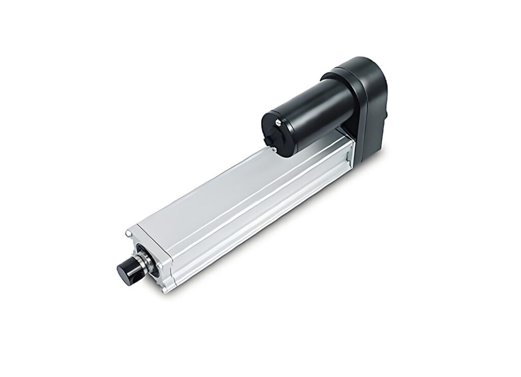
Option A: Linear Actuators
- 最適な用途: Elevation axis (north-south tilt)
- Specifications needed:
- Stroke length: 150–300mm (depending on panel size and desired tilt angle)
- Force capacity: Minimum 150 lbs (68kg) for small panels, 500+ lbs for larger arrays
- Voltage: 12V or 24V DC
- Duty cycle: 25% minimum for intermittent tracking movement
- Advantages: Simple installation, built-in limit switches available, cost-effective
- 例: A 6-inch stroke actuator with 150 lbs force can effectively tilt a 90W panel through its full range.
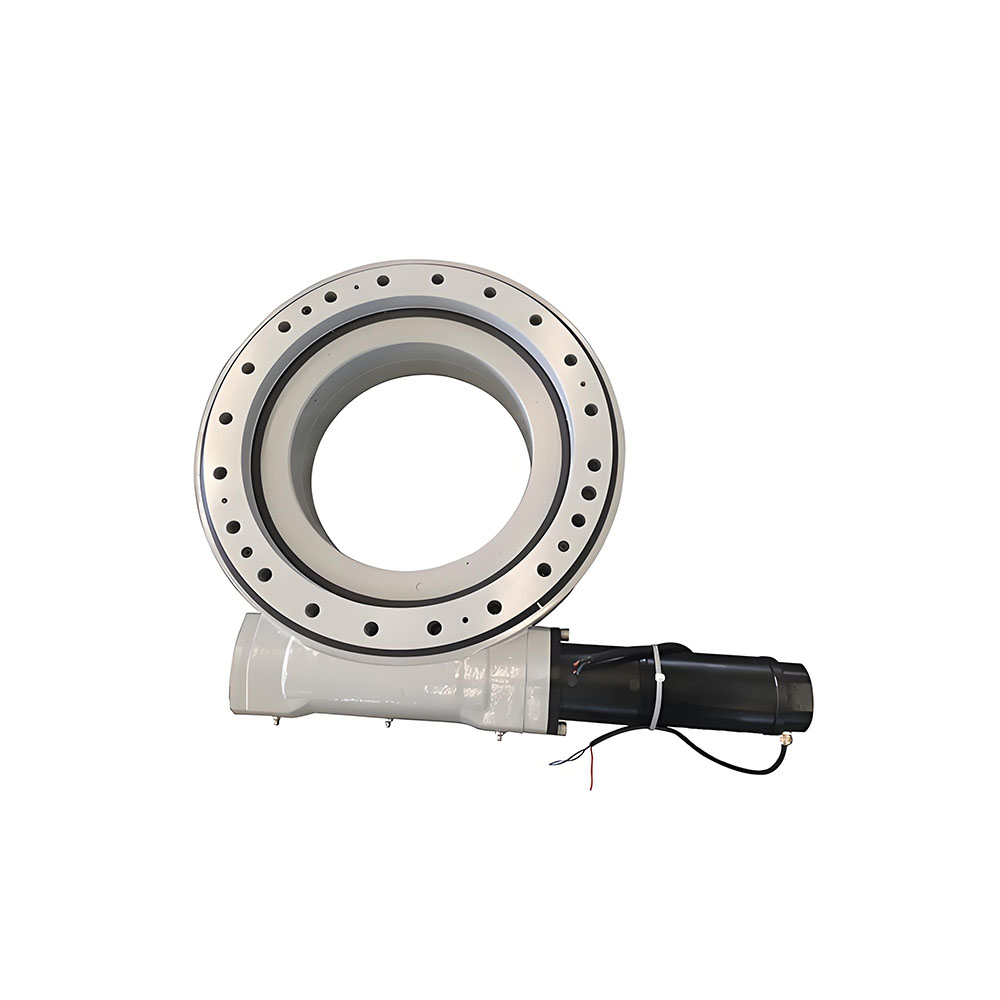
Option B: Slewing Drives
- 最適な用途: Azimuth axis (east-west rotation)
- Specifications needed:
- Output torque: Calculate based on panel weight and wind load
- Gear ratio: 30:1 to 60:1 for precise, slow movement
- Worm drive type for self-locking capability
- Advantages: 360° rotation capability, high load capacity, built-in holding torque
- Note: For small DIY projects, a modified slew drive from satellite dish mounts or telescope trackers can be repurposed cost-effectively.
Drive Selection Decision Matrix:
表格
| 要素 | リニアアクチュエータ | Slewing Drive |
|---|---|---|
| 料金 | $30–$380 | $50–$800 (DIY/repurposed) |
| Rotation range | Limited (0–90° typical) | 360° continuous |
| Holding power | Moderate (requires brake) | Self-locking (worm gear) |
| Best application | Elevation tilt | Azimuth rotation |
| メンテナンス | 低い | Low-moderate |
3. Motor Control and Drivers
Your solar tracking system requires motor drivers that can handle bidirectional control:
H-Bridge Motor Drivers:
- L298N: Basic, handles 2A per channel, good for small motors
- BTS7960: High-current (43A capability), integrated heatsink, ideal for larger actuators and slew drives. Multiple units can be combined for dual-axis control.
- WASP Motor Controller: Specifically designed for actuator control with PWM input, compatible with Arduino servo libraries.
Controller Specifications to Consider:
- Input voltage: Match your actuator/servo voltage (12V or 24V typical)
- Continuous current: 2× your motor’s rated current for safety margin
- PWM control capability for smooth, variable-speed positioning
Controller Selection: The Brain of Your Solar Tracker
Option 1: Arduino-Based Systems (Beginner-Friendly)
The Arduino platform offers the most accessible entry point for DIY solar tracker projects:
Recommended boards:
- Arduino Uno: $8–$12, extensive code libraries, 14 I/O pins
- Arduino Nano: Compact, ideal for permanent installation
- ESP32: $5–$8, built-in WiFi/Bluetooth for IoT monitoring and remote control.
Key Components for Arduino Systems:
- Light sensors: 4× LDRs (Light-Dependent Resistors) arranged in cardinal directions
- Real-time clock: DS3231 or DS1307 module for time-based positioning
- Compass module: HMC5883L for absolute orientation reference
- Irradiance sensor: Optional, for measuring actual solar intensity
Sensor Layout:
The controller compares light intensity from opposing sensors. When the difference exceeds a tolerance threshold (typically 20–50 analog units), the corresponding motor adjusts panel position.
Option 2: STM32-Based Systems (Advanced)
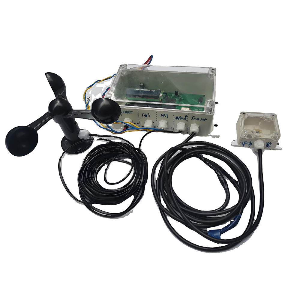
For more demanding applications, STM32 microcontrollers offer:
- Higher processing power for complex astronomical algorithms
- Multiple PWM outputs for precise motor control
- CAN bus capability for future expansion
- Research shows STM32-based trackers can achieve 27.97% efficiency improvement over static panels.
Control Algorithm Approaches
Method 1: Light-Tracking (Active Mode)
- Continuously compares LDR readings
- PID-style correction for smooth movement
- Simple to implement, responsive to local conditions
- Risk: Can be fooled by reflections or cloud edges
Method 2: Astronomical Calculation (Passive Mode)
- Calculates sun position from date, time, latitude, and longitude
- Uses PSA algorithm or SolarPosition library
- Immune to false light sources
- Requires accurate RTC and geographic coordinates
Method 3: Hybrid Approach (Recommended)
- Uses astronomical calculation as primary positioning
- LDR sensors for fine-tuning and cloud detection
- Returns to calculated position if sensors disagree significantly
Complete Wiring Architecture
Power System Design
A reliable solar tracking system needs independent power for the control electronics:
Recommended Configuration:
- Main battery: 12V 7Ah lead-acid or 3.7V 18650 Li-ion pack
- Charging: Dedicated solar charge controller (Genasun GV-10 or similar)
- Voltage regulation: LM7805 or buck converter for 5V logic supply
- Motor power: Separate 12V/24V supply from battery, fused independently
Critical Wiring Sequence:
- Connect battery to charge controller first
- Connect load (tracker electronics) to controller load terminals
- Connect PV array to controller
- Verify all polarities before powering motors
Fusing Requirements:
- Battery to controller: 10A fuse
- Motor circuits: 4A slow-blow fuses per axis
- Logic supply: 1A fuse
Limit Switch Integration
安全性 リミットスイッチ are essential to prevent mechanical damage:
種類だ:
- Mechanical microswitches: Schaltbau S880 or similar, with positive opening operation for reliability
- Magnetic proximity sensors: NPN type, 5mm sensing distance
- Built-in actuator limits: Many リニアアクチュエータ include internal limit switches
Wiring Methods:
- Method A: Switches in motor power circuit (hardware interlock)
- Method B: Signal to controller (software-controlled stop)
- Method C: Combined approach for redundancy
The controller uses limit switches for homing reference—when triggered, the system knows its absolute position and can recalibrate.
Step-by-Step Build Process
Phase 1: Mechanical Construction (Days 1–2)
- Cut and weld steel frame components
- Install central pivot bearing for azimuth axis
- Mount elevation hinge with リニアアクチュエータ attachment points
- Attach panel mounting rails with proper grounding
- Paint all steel with weather-resistant coating
Phase 2: Drive Installation (Day 3)
- Install slew drive or azimuth rotation mechanism
- Mount リニアアクチュエータ for elevation control
- Connect drive shafts with flexible couplers if needed
- Test manual movement through full range
- Install limit switches at mechanical extremes
Phase 3: Electronics Assembly (Day 4)
- Mount controller board in weatherproof enclosure (IP65 minimum)
- Install sensor array on panel frame (shielded from direct rain)
- Route motor cables through cable chains or flexible conduit
- Connect power distribution with proper fusing
- Install battery and charge controller in separate vented compartment
Phase 4: Programming and Calibration (Days 5–6)
- Upload tracking firmware to controller
- Set geographic coordinates and timezone
- Calibrate sensor thresholds in actual sunlight
- Verify limit switch operation
- Test full day cycle tracking performance
Cost Breakdown and ROI
DIY vs. Commercial Comparison
表格
| System Type | Energy Gain | Cost (Materials) | Payback Period |
|---|---|---|---|
| Fixed tilt | ベースライン | $200–$350/kWp | 13 years |
| Single-axis DIY | +15–25% | $30–$50 | 適度 |
| Dual-axis DIY | +30–35% | $50–$80 | Best for DIY |
| Commercial tracker | +20–30% | $80–$180/kWp | 15–19 years |
DIY 太陽追尾システム can cut installation costs by 50–70% compared to commercial alternatives while delivering comparable performance. For a small system under $50 in materials, the payback is typically under 2 years when accounting for increased energy production.
Sample Budget for Personal DIY Tracker
Maintenance and Troubleshooting
Monthly Tasks
- Clean PV panels with water (early morning or evening)
- Inspect リニアアクチュエータ そして slew drive for debris
- Check all bolt tightness after windy conditions
- Verify tracker returns to east position overnight
Common Issues and Solutions
| Symptom | Likely Cause | 解決 |
|---|---|---|
| Tracker stops mid-day | Insufficient power | Check battery voltage, clean panels |
| 不規則な動き | Sensor drift | Recalibrate LDR thresholds |
| Motor runs but no movement | Mechanical binding | Check for seized bearings or bent frame |
| No night return | Limit switch fault | Test switch continuity, check wiring |
| Low energy output | Tracking misalignment | Verify sensor orientation, check for shading |
Final Recommendations
For your personal DIY solar tracking system project:
- Start simple: Build a single-axis tracker first to validate your mechanical design before adding complexity
- Invest in structure: The frame and bearings are your most critical long-term components—don’t compromise on weatherproofing
- Use quality linear actuators: Built-in limit switches and weatherproofing are worth the extra cost for outdoor installations
- Plan for expansion: Choose a controller (ESP32 or STM32) that can support future IoT monitoring and multiple panel arrays
- Safety first: Always include hardware limit switches independent of software control, and design for local wind loads
- Document everything: Photograph wiring before closing enclosures, record calibration values, and keep spare fuses on hand
A well-built DIY solar tracker と リニアアクチュエータ そして slew drives can deliver 30%+ energy gains for under $200 in materials, making it one of the most rewarding renewable energy projects for technically-minded enthusiasts.