As the global demand for renewable energy surges, solar tracking system technology has become a cornerstone of maximizing photovoltaic (PV) and concentrated solar power (CSP) efficiency. However, one of the most critical challenges facing solar tracking system deployments—particularly in high-wind regions—is structural integrity under extreme weather conditions. Wind loads can cause catastrophic failures, misalignment, and permanent deformation of tracking structures, leading to significant revenue loss and safety hazards. This article provides an in-depth analysis of wind resistance enhancement strategies tailored for single-axis tracking systems, dual-axis tracking systems, and concentrated solar power (CSP) tracking systems, offering actionable engineering insights for manufacturers, EPC contractors, and project developers.
1. Single-Axis Solar Tracking System Wind Resistance Strategies
Single-axis solar tracking systems, which rotate along one axis (typically north-south), are widely deployed in utility-scale PV plants due to their optimal balance of cost and energy yield improvement. Their elongated, linear structure makes them particularly vulnerable to aerodynamic flutter and torsional wind loads.
1.1 Aerodynamic Profile Optimization
The primary defense against wind damage in a single-axis solar tracking system begins with aerodynamic design. Streamlined torque tubes and purlin configurations reduce drag coefficients by up to 30% compared to traditional box-section designs. Implementing a stow position strategy—where modules rotate to a horizontal or near-horizontal orientation during high-wind events—dramatically reduces the sail area exposed to wind pressure. Modern controllers integrate anemometers and wind vanes to trigger automatic stow protocols when wind speeds exceed 15–20 m/s, depending on local wind zone classifications.
1.2 Structural Reinforcement Techniques
Torque Tube Enhancement: Upgrading from standard steel tubes to high-strength, low-alloy (HSLA) steel with yield strengths exceeding 355 MPa provides superior resistance to bending and torsion. Increasing tube wall thickness at critical span sections—particularly at drive joints and bearing points—mitigates stress concentration.
Foundation and Pile Design: In wind-prone regions, driven piles or helical anchors should penetrate at least 1.5 times the standard depth, with reinforced concrete pile caps to distribute overturning moments. Geotechnical surveys must account for both sustained wind loads and gust factors specific to the installation site.
Damping Systems: Installing viscoelastic dampers or tuned mass dampers at module mounting points absorbs resonant vibrations caused by vortex shedding, preventing fatigue failure in long-span single-axis solar tracking system arrays.
1.3 Drive Train and Bearing Upgrades
Slew drives and linear actuators must be oversized by a minimum 1.5 safety factor for wind load conditions. Self-locking worm gear mechanisms prevent back-driving during wind gusts, while sealed, maintenance-free bearings with IP65+ ratings ensure operational reliability in dusty, high-wind environments.
2. Dual-Axis Solar Tracking System Wind Resistance Strategies
Zweiachsig solar tracking system installations, which track both azimuth and elevation angles, achieve the highest energy yield but present the greatest structural complexity and wind exposure due to their elevated, multi-directional orientation capabilities.
2.1 Elevation-Axis Stow Positioning
Unlike single-axis systems, dual-axis trackers must execute a rapid “table-top” stow position—where modules lie flat and parallel to the ground—during high-wind events. This orientation minimizes both drag and lift forces. The stow mechanism must achieve full positioning within 90 seconds of wind threshold detection, requiring high-torque DC motors or hydraulic actuators with emergency power backup systems.
2.2 Azimuth Drive and Central Pivot Reinforcement
The central pedestal and azimuth ring gear represent the highest-stress components in a dual-axis solar tracking system. Reinforcement strategies include:
- Pedestal Design: Using tubular steel columns with diameter-to-thickness ratios optimized for buckling resistance, filled with high-strength concrete for added mass and damping.
- Ring Gear Protection: Case-hardened steel ring gears with induction-hardened tooth profiles withstand repetitive wind-induced torque spikes. Integrated torque limiters protect the drive train from overload during sudden gusts.
- Cross-Bracing: X-bracing or K-bracing between the elevation frame and azimuth platform increases torsional rigidity, preventing racking deformation under uneven wind pressure.
2.3 Module Mounting and Load Distribution
Dual-axis trackers typically support 20–40 modules per tracker, creating substantial point loads. Using continuous aluminum rail systems with clamping interfaces rather than discrete L-foot brackets distributes wind loads evenly across the module frame. Additionally, module frames should be certified to IEC 61215 static mechanical load tests of 5,400 Pa (equivalent to approximately 60 m/s wind pressure).
2.4 Control System Intelligence
Advanced dual-axis solar tracking system controllers employ predictive algorithms that integrate meteorological data feeds, enabling pre-emptive stow positioning before wind fronts arrive. Machine learning models trained on site-specific wind patterns optimize stow trigger thresholds, balancing energy production against structural safety margins.
3. Concentrated Solar Power (CSP) Tracking System Wind Resistance Strategies
CSP solar tracking system technology—encompassing parabolic troughs, solar power towers with heliostat fields, and dish-Stirling systems—operates under fundamentally different mechanical constraints than PV trackers. These systems concentrate sunlight onto receivers or towers, requiring precise optical alignment and massive reflector surfaces that are highly sensitive to wind-induced deformation.
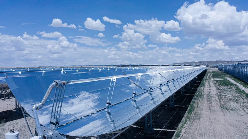
3.1 Parabolic Trough CSP Trackers
Parabolic trough solar tracking system arrays consist of long, curved reflectors mounted on torque-box structures. Wind resistance enhancement focuses on:
- Torque Box Stiffening: Space-frame torque boxes constructed from welded steel trusses with diagonal bracing resist both torsional and lateral wind loads. Finite element analysis (FEA) should validate designs against 3-second gust wind speeds per ASCE 7-22 standards.
- Glass Mirror Support: Laminated glass mirrors with reinforced mounting clips prevent detachment under suction pressures. Mirror aperture areas should be segmented into manageable panels to reduce individual wind exposure.
- Hydraulic Drive Systems: Centralized hydraulic drive systems with accumulator-based emergency positioning can execute rapid stow-to-wind operations, rotating troughs to minimize cross-sectional exposure.
3.2 Heliostat Field Tracking Systems
Heliostat solar tracking system fields comprise thousands of individual reflectors, each requiring precise two-axis positioning. Wind resilience strategies include:
- Pedestal and Foundation: Reinforced concrete piers with embedded anchor bolt cages resist overturning moments. Pedestal heights are minimized to reduce the moment arm, though optical clearance requirements dictate practical limits.
- Reflector Back Structure: Honeycomb aluminum or composite back structures provide high stiffness-to-weight ratios, minimizing gravitational sag while resisting wind-induced deflection. Reflector curvature accuracy must be maintained within ±2 mrad under design wind loads to preserve optical focus.
- Field Layout Optimization: Computational fluid dynamics (CFD) modeling of heliostat arrays identifies sheltering effects between rows. Staggered layouts and increased row spacing in prevailing wind directions reduce cumulative wind loads on downstream heliostats.
- Emergency Stow Protocols: Heliostat fields implement hierarchical stow commands—edge rows stow first to create windbreaks for interior units. This cascaded approach prevents simultaneous mechanical loading across the entire solar tracking system field.
3.3 Dish-Stirling and Central Receiver Systems
For dish concentrator solar tracking system units, the parabolic dish acts as a large sail. Wind resistance is achieved through:
- Dish Structural Ribs: Radial and circumferential ribs fabricated from aluminum extrusions or pultruded fiberglass maintain parabolic accuracy under wind pressure.
- Receiver Arm Bracing: The central receiver support arm—extending from the dish focal point—requires tubular truss bracing to prevent oscillation-induced receiver misalignment.
- Foundation Mass: Dish-Stirling systems benefit from massive concrete ballast foundations (often exceeding 10 tonnes) that provide both stability and vibration damping.
4. Universal Best Practices Across All Solar Tracking System Types
Regardless of tracker architecture, the following principles apply universally to enhance wind resistance in any solar tracking system:
4.1 Site-Specific Wind Load Analysis
Conduct comprehensive wind resource assessments using meteorological towers or LiDAR systems for at least 12 months prior to design finalization. Apply appropriate gust factors, directionality coefficients, and topographic multipliers per IEC 62817 (PV trackers) or local building codes.
4.2 Material Selection and Corrosion Protection
Hot-dip galvanized steel (minimum 85 μm zinc coating) or aluminum alloys (6005-T5 or 6061-T6) with anodized finishes ensure longevity in coastal or high-humidity wind environments. Stainless steel fasteners (A2-70 or A4-80 grade) prevent galvanic corrosion at dissimilar metal interfaces.
4.3 Regular Inspection and Maintenance Protocols
Implement annual structural inspections focusing on bolt torque verification, bearing lubrication, and foundation settlement monitoring. Post-storm inspections must assess stow mechanism functionality and module/frame deformation.
4.4 Certification and Testing Standards
Ensure solar tracking system designs comply with IEC 62817 (design qualification for PV trackers), UL 3703 (safety standard for PV trackers), and ASCE/SEI 7 (minimum design loads for buildings and other structures). Wind tunnel testing of scaled models or full-scale prototype testing provides empirical validation of analytical models.
Abschluss
Enhancing wind resistance in solar tracking system installations is a multidisciplinary endeavor integrating aerodynamic engineering, structural mechanics, materials science, and intelligent control systems. Single-axis systems benefit from streamlined stow positions and torque tube reinforcement; dual-axis systems require robust pedestal designs and rapid-response elevation drives; CSP trackers demand optical-precision structures with specialized emergency positioning protocols. By implementing the strategies outlined in this guide, project stakeholders can significantly extend system lifespans, reduce O&M costs, and ensure reliable energy generation even in the most challenging wind environments. As the solar tracking system market continues to expand into high-wind coastal and desert regions, wind-resistant design will remain a critical competitive differentiator for technology providers and EPC integrators worldwide.