You are struggling with the loss of kilowatt hours every day. The shadow between rows stole the power generation. High wind events force the system to retract more frequently than you would like. Debugging for too long will consume cash. These are not abstract challenges, they directly impact the levelized cost of electricity (LCOE) of your project and your bottom line. The core of the problem often lies in the obvious: the driving mechanism of your solar tracker.
Why is the mechanical structure of the tracker crucial for photovoltaic efficiency
Compared to arrays with fixed tilt angles, solar tracking systems can increase energy production. They maximize the solar irradiance on the components through controlled azimuth and elevation movements. In utility scale power plants, this difference can typically reduce LCOE by a few percentage points throughout the entire lifecycle of the project. You can feel this in your cash flow.
- Single axis trackers typically scan in an east-west direction to follow the trajectory of the sun in the sky.
- The dual axis tracker has added elevation control to more accurately align with the sun’s normal, thereby improving performance during early morning and evening hours as well as seasonal consistency.

Internally, the two major drive series bear the heavy workload:
- Rotary drive provides rotational motion to control the azimuth angle.
- Linear actuators provide linear travel to control elevation angle.
If you choose the wrong mechanism for your load and environment, you will lose energy, incur more O&M costs, and increase the likelihood of unplanned downtime.
Mechanical principle of rotary drive in solar tracking
Rotary drive is a compact and integrated rotating unit. It combines the gear transmission system, rolling bearings, and sealed housing together to provide high torque rotational motion in a single package. In photovoltaic trackers, you most commonly see rotary drives used to handle azimuth on dual axis platforms or primary rotation in certain single axis designs.
Working principle:
- The motor drives the gear set and rotates the internal bearing ring.
- The bearing supports radial and axial loads from the tracker structure.
- The integrated casing protects the mechanical structure, simplifying installation and maintenance.
Advantages of using rotary drive:
- High torque density, suitable for long rows and heavy upper structures.
- Accurate rotation control ensures tracking accuracy even in strong winds.
- Compact integration reduces the number of components and installation time.
Factors to consider:
- The gear transmission system must control the backlash to maintain directional accuracy in reverse rotation and gusts.
- Proper lubrication and sealing are crucial in dusty or coastal environments.
- You should match the motor and gear ratio with wind load and inertia to prevent the drive from stalling during gusts or overspeeding during release.
In short, rotary drive is suitable for azimuthal motion, and in these applications, rotational stiffness and torque can determine the performance success or failure of the tracker.
Linear actuator for tracking solar panels
Linear actuators convert motor rotation into linear motion. Most solar applications use screw based designs, such as ball screws or trapezoidal screws. The motor rotates the screw, the nut advances, and the push rod extends or retracts to set the elevation angle of the component.
The reason why the team chose linear actuators:
- High cost-effectiveness and compact structure, suitable for small and medium-sized arrays.
–Simple integration, easy to install and control. - Reliable travel with position feedback for precise tilt angle.
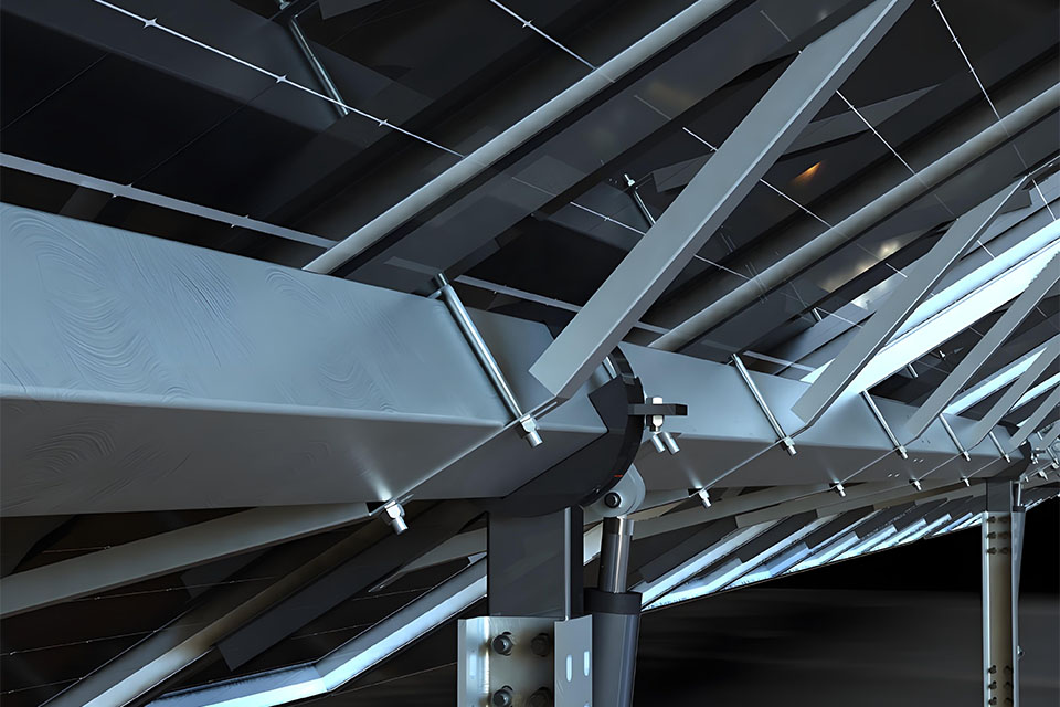
Attention:
- If the actuator is subjected to bending force instead of pure axial force, lateral loads will shorten its lifespan.
- Dust and moisture require sufficient IP protection level and sturdy sealing.
- There are work cycle limitations. You should choose actuators of appropriate size to avoid thermal overload during frequent movement or high wind activity.
Linear actuators perform well on the elevation axis because in these applications, the pure axial load and shorter stroke make wear predictable and easy to repair.
Side by side comparison: rotary drive vs. linear actuator
Your choice depends on the type of motion, structural load, environment, and control objectives. This overview will help you make decisions.
| Attributes | Rotary Drive | Linear actuator |
|---|---|---|
| Motion type | Rotation (azimuth) | Linear stroke (elevation) |
| Typical tracker axis | Uniaxial or biaxial east-west rotation | Uniaxial or biaxial tilt/elevation angle |
| Core mechanism | Integrated gear transmission system with large bearings and sealed housing | Motor driven screws (ball or trapezoidal), push rods, and seals |
| Torque behavior | High torque density, suitable for long and heavy arrays | High axial force, suitable for compact elevation loads |
| Anti reverse drive capability | Gear transmission system can resist reverse drive, helping to maintain position in gusts of wind | Screw mechanism designed to resist reverse drive based on pitch and nut |
| Backclearance and Accuracy | Gear backlash must be controlled to ensure tracking accuracy | The low backlash of ball screws improves elevation accuracy |
| Load Handling | Handling radial and axial combined loads from tracker structures | Best performance under pure axial loads, with minimal lateral forces |
| Maintenance instructions | Lubrication and sealing checks can maintain the health of gears and bearings | Check the sealing of screws and push rods, and verify the health status of the motor related to the working cycle |
| Environmentally sealed/IP | Sealed casing supports strong IP protection | IP rating varies by model and needs to be carefully selected for dust or water environments |
| Wind load management | Strong torque and rotational stiffness reduce the frequency of retraction | Sufficient to handle elevation loads, which typically withstand lower wind torques |
| Cost Overview | Shows high initial cost in large arrays, but low lifetime risk in harsh environments | Low initial cost, especially in small commercial or residential arrays |
| Typical use case | Azimuth axis and dual axis platform for utility scale | Elevation axis and small to medium-sized arrays, where simplicity is the advantage |
This is the core of the driving mechanism for solar trackers. Rotation is used for azimuth, while linearity is used for elevation. Each mechanism brings unique behaviors that affect energy production and reliability.
Efficiency, accuracy, and reliability
- Tracking accuracy drives energy production. The appropriately sized rotary drive paired with intelligent control can tightly maintain the azimuth angle, thereby increasing the power generation during the morning and evening periods. Linear actuators provide repeatable elevation angles, stabilizing the daily power generation curve.
- Durability in dusty and high-temperature environments favors sealing mechanisms with sturdy bearings and gear transmission systems. A well sealed rotary drive reduces abrasive intrusion and helps maintain accuracy. Linear actuators with appropriate specifications, IP rating, and dust scraper can resist dust and moisture.
- When you align the mechanism with the load, maintenance costs will decrease. A rotary drive with the correct gear ratio and torque margin requires less intervention on the long row. A linear actuator that avoids lateral loads and operates within its working cycle can maintain motor cooling and screw cleanliness.
You can feel this pattern: the right mechanism, the right axis, the right control.
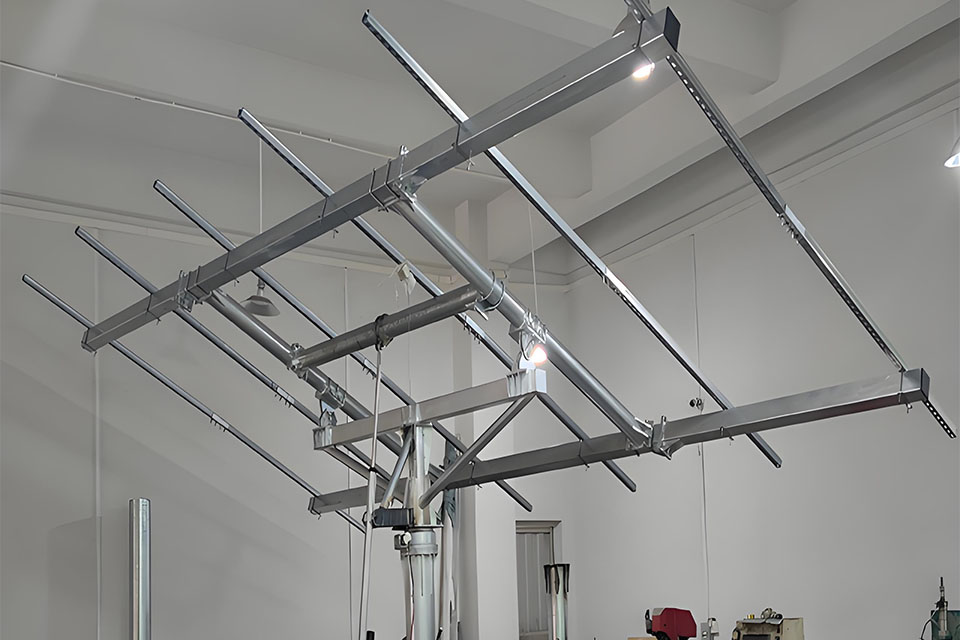
Financial perspective: Initial investment vs. lifetime cost
Your finance team cares about the overall situation. Initial capital expenditures are important, but lifetime costs typically determine the ultimate winner.
- For large azimuth axes, rotary drives typically have a higher unit price. But in windy areas, you can recoup this investment by reducing storage events and increasing normal operating time.
- For elevation axes or small arrays, linear actuators typically outperform in initial cost. By selecting the appropriate IP rating and managing the work cycle during the storm season, you can maintain this advantage.
When simulating 10-20 years of operation, driver selection will affect LCOE. Less misalignment, less on-site maintenance, and more kilowatt hours per year. This account has been calculated.
Choosing the Right Mechanism: Practical Checklist
Use this checklist to make a confident, engineering first decision.
- Define row length, superstructure mass, and inertia for each axis.
- Simulate the wind distribution and retraction strategy of the site. Leave a margin for torque and force.
- Assess environmental risks: dust, salt spray, snow, temperature fluctuations, and water intrusion.
- Specify the tracking accuracy target in degrees or milliradians and map it to the back gap and sensor resolution.
- Match the work cycle with controller behavior (including collapse, wake-up, and cloud edge events).
- Plan and maintain channels and spare parts: bearings, seals, screws, motors, and controllers.
- Align initial costs with lifetime value: estimate downtime, energy losses, and operational costs.
If you want to gain a deeper understanding of subsystem selection, please browse our component and assembly product portfolio, which includes drivers, controllers, and brackets. You can also view comprehensive options for large power plants on our dedicated utility page. Please refer to our page on the complete utility scale solar tracking system, which provides detailed end-to-end content from the grid, actuator to controller.
- Learn about our complete tracker stack and engineering components in the SolPath Tracker Component Center: Integrated Tracker Component for Solar Tracking Systems .
- In our utility scale solar tracker solution Explore large-scale project configurations.
- In our Installation and Maintenance Support View installation planning and service workflow in the middle.
- For compact arrays, please compare our options for residential and small commercial photovoltaic linear actuator trackers .
The secret to higher output: the combination of intelligent control and sturdy machinery
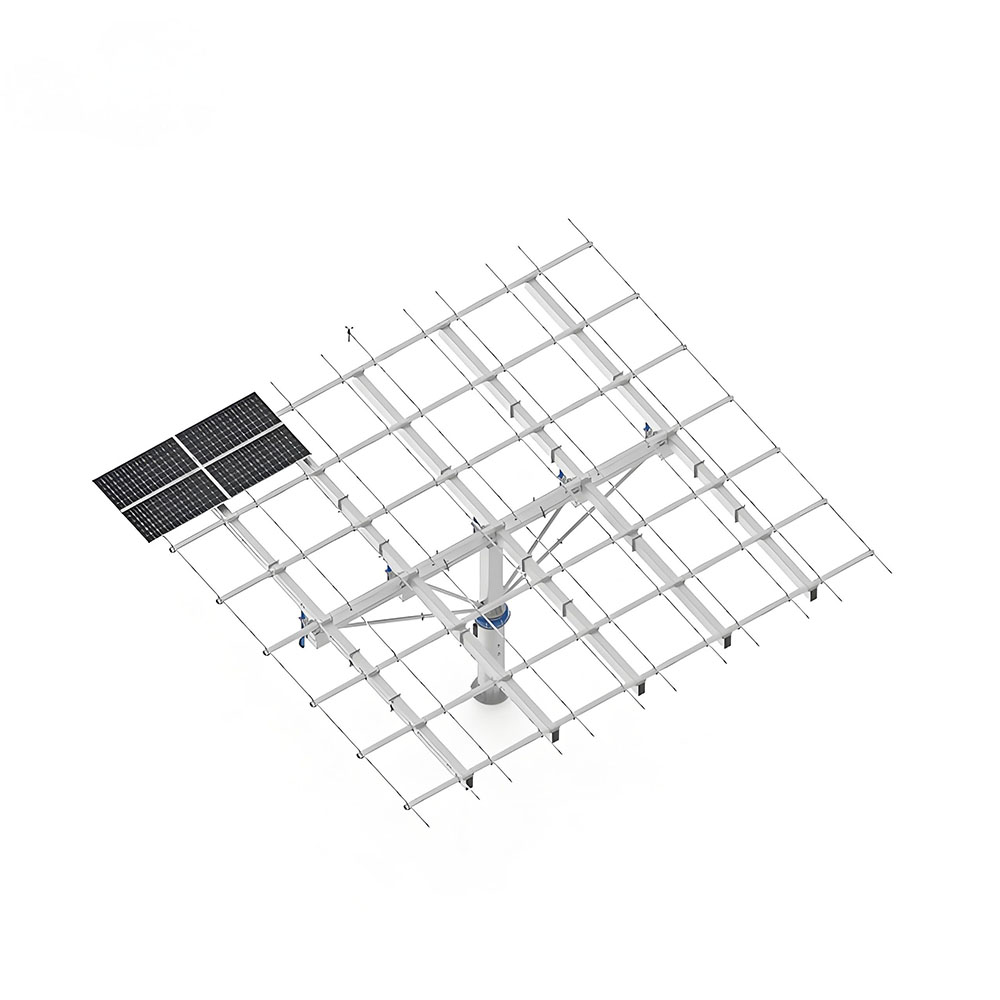
Machinery sets limits, while software captures value. You close this loop through intelligent control.
SolPath combines validated driver hardware with control technology designed for actual sites:
- The anti shadow tracking algorithm reduces inter row shadows under complex solar angles and scattered light conditions. You can expose more components to sunlight, thereby increasing daily energy production.
- Remote debugging has shortened the construction period. The team can configure controllers, validate sensors, and adjust tracking curves without waiting for on-site firmware updates.
–Airborne software upgradeprovides new features and improvements for your device group. You can improve elasticity and performance over time without touching each row.
In practice, this seems quite simple. You deploy a robust rotary drive on the azimuth axis in windy areas. You use a linear actuator at an elevation angle with a pure axial load path. You give control to an intelligent tracker brain that optimizes angles and folding behavior. You have reduced shadow loss, minimized on-site repairs, and squeezed out more kilowatt hours from each sunrise.
Towards the future: intelligent tracking, Internet of Things, and predictive maintenance
The next decade belongs to trackers that can learn. Sensors stream load, vibration, and position data to the cloud. The controller adjusts the folding threshold based on the actual wind conditions. Model predicts component wear. Your operations team takes action before a malfunction causes downtime.
SolPath’s architecture already supports remote diagnosis and full device group adjustment. As AI driven analytics technologies become increasingly mature, you will see:
- Adaptive tracking that balances power generation and gust risk every minute.
- Predictive maintenance window for replacing drives or actuators before failure.
- Firmware updates that improve control accuracy and reduce energy waste.
All of this relies on a solid mechanical foundation. You cannot eliminate backlash or compensate for insufficient torque through prediction. You need to specify the drivers and actuators correctly in order for intelligent control to shine.
FAQ: Rotary drive and linear actuator in solar energy
- What is the typical lifespan of a solar tracker actuator?
- When you match the mechanism with the load and environment, the design lifespan is typically 10-20 years. Through planned maintenance, sealed rotary drives and appropriately rated linear actuators can achieve this deadline.
- Can I use these actuators to convert a fixed array into a tracking system?
- Yes, it is. You need to add appropriate rotary drives or linear actuators, as well as controllers, sensors, and brackets. Before renovation, you should evaluate the foundation load and wiring. For options on different array sizes, please refer to our Ground Installation Tracking Solution.
- What is the power consumption of these actuators?
- Power consumption is intermittent. The motor consumes energy during movement and retraction, leaving a lower parasitic load when stationary. Correctly adjusting torque and force, coupled with intelligent retraction strategies, can minimize energy costs relative to power generation gains.
Summary
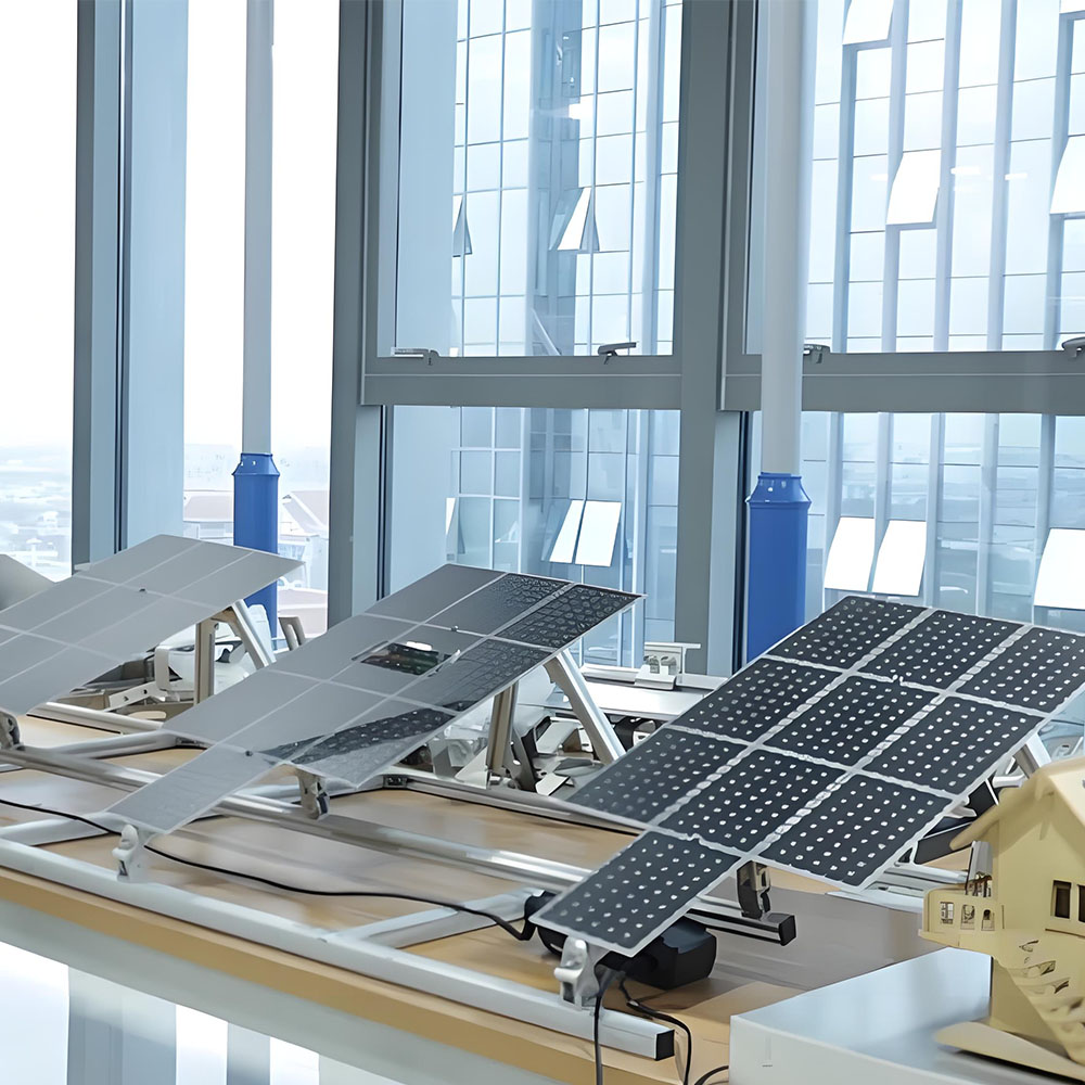
The mechanical structure of the tracker can bring returns. Rotary drive provides rigid, high torque azimuth control for long rows and harsh wind conditions. Linear actuators provide pure and cost-effective elevation motion for compact arrays. Pair them with intelligent software that can reduce shadows and simplify debugging. SolPath integrates the entire technology stack together: robust hardware, intelligent control, and support for remote operations. You have maximized energy production and reduced lifetime costs, thereby driving the LCOE of your project in the right direction.
If you want to compare configurations based on array size and site conditions, please start from our product portfolio page and then talk to our engineering team. We help you match the mechanical structure with your load and weather, allowing your power station to generate more electricity with fewer accidents.